How MEP Teams Can Update Air Handling Unit Duct Connections and Transitions in AutoCAD Faster
AutoMEP Team,
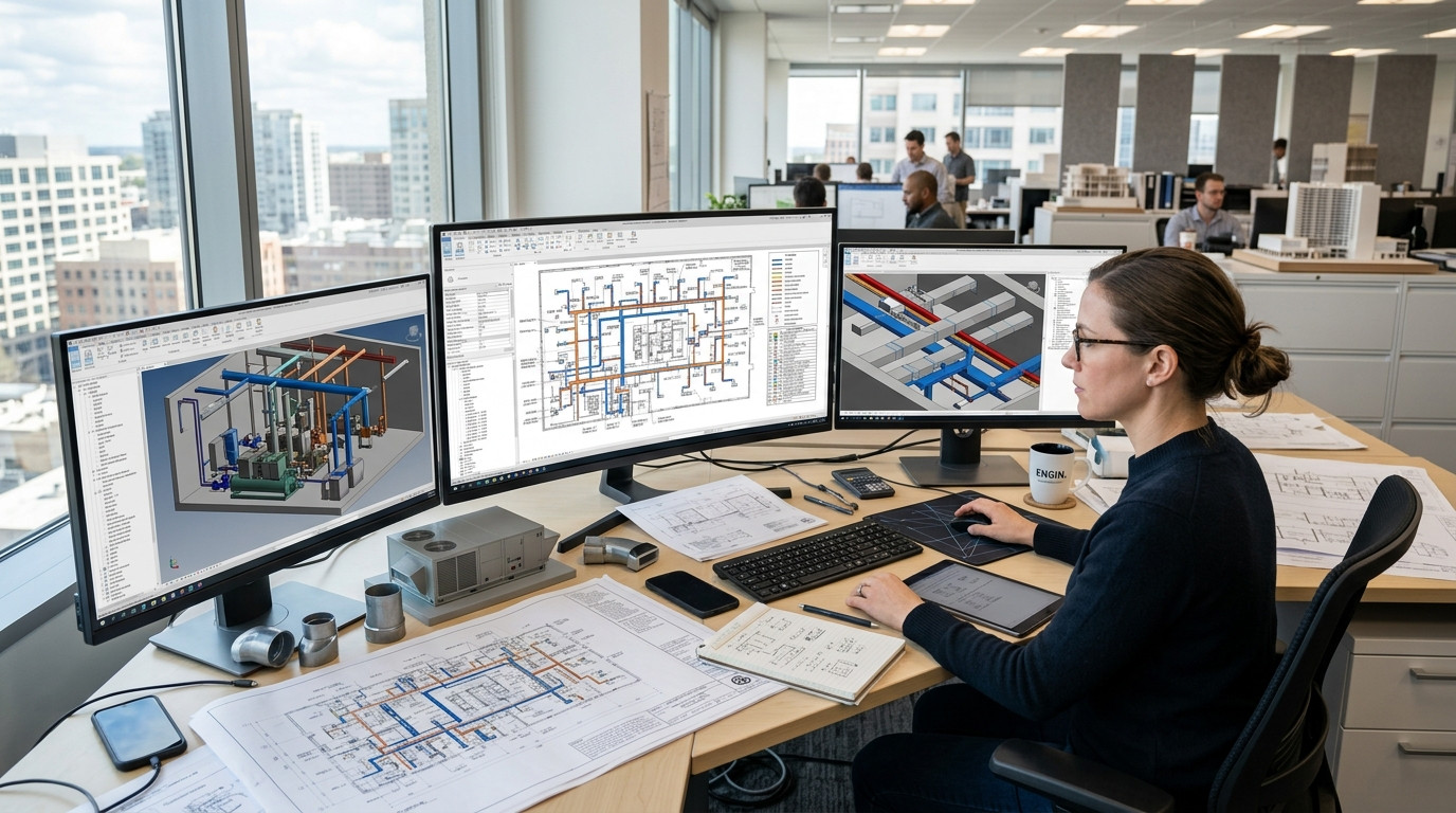
When a mechanical equipment selection changes late in design, the mechanical room drawings often absorb the heaviest drafting hit. An air handling unit (AHU) might be switched from an end discharge to a top discharge, or the manufacturer cut sheet arrives with slightly shifted casing dimensions, a revised supply fan CFM, or a different supply discharge collar size. In standard 2D AutoCAD workflows, updating an AHU supply and return duct connection is rarely as simple as sliding a block. Drafters and project engineers usually find themselves manually redrawing eccentric duct transitions, nudging canvas flexible connections, adjusting acoustic duct lining callouts, shifting smoke dampers, and realigning downstream duct mains to avoid structural columns.
The Repetitive Drag of AHU Connection Revisions
In commercial building mechanical rooms, space is at a premium. Supply and return duct mains departing an air handling unit must thread between structural steel, piping racks, cable trays, and maintenance clearance envelopes. When equipment revisions occur, drafting technicians must execute dozens of synchronized modifications across the DWG file:
- Resizing supply and return discharge collars to match updated unit dimensions.
- Recalculating and drafting eccentric or concentric duct transitions within strict length-to-slope ratios to prevent turbulence and excessive pressure drop.
- Repositioning flexible duct connectors, balancing dampers, and fire or smoke dampers while maintaining required maintenance clearances.
- Shifting connected rectangular duct mains and elbow fittings downstream without clashing into adjacent structural beams or piping runs.
- Updating dimensional annotations, duct size tags, CFM callouts, and mechanical equipment schedule tags across multiple sheets.
Because these edits involve closely coordinated geometry, drafters often spend hours breaking polylines, trimming intersections, and re-tagging sizes by hand. A single equipment submittal update can disrupt drafting schedules and inflate non-billable revision hours across the engineering team.
Why Traditional AutoCAD Solutions Fall Short for Mechanical Rooms
Engineering firms have attempted to speed up this work using internal standards, custom scripts, or third-party tools, but each approach introduces operational bottlenecks. Custom AutoLISP routines often choke when dealing with non-standard duct transitions, nested equipment blocks, or angled takeoffs commonly found in dense mechanical rooms. Complex third-party CAD add-ons demand seat licenses, continuous version maintenance, and extensive staff training, which creates inconsistent workflows across the office. Furthermore, relying on senior CAD managers to troubleshoot broken macros diverts high-value technical leadership away from project QA and delivery milestones.
MEP drafting teams need an agile way to execute repetitive duct updates directly inside their native DWG files without rolling out intrusive software plugins or forcing engineers to become programmers.
Automating AHU Duct Edits with Natural-Language Prompts in AutoMEP
Instead of manually redrawing every transition and fitting, teams can use AutoMEP to translate natural-language design instructions into precise drawing modifications. Built specifically for MEP engineering workflows, AutoMEP reads drawing layouts and programmatically updates duct geometry, fittings, and tags directly inside AutoCAD DWG files.
For example, an engineer or CAD manager can provide a straightforward instruction such as:
- Update the supply duct discharge transition on AHU-1 to 48 by 24 inches, maintain a 3-foot transition length, reattach the flexible connector, and shift the downstream 48x24 main duct run 6 inches north to clear the column.
- Revise the return air plenum connection to match the new 36 by 30 inch casing opening, adjust the duct elbow fitting, and update the air balancing and size tags accordingly.
AutoMEP interprets the spatial relationships in the DWG file, updates the components according to standard duct construction rules, and preserves your firm's existing layers, linetypes, and dimension styles. There are no external scripts to debug and no custom software to deploy on local workstations.
Preserving CAD Standards, Clearances, and Accountability
A primary concern for CAD managers adopting automation is maintaining strict quality control. Drafting shortcuts can easily lead to missed code clearances or uncoordinated collisions in the field. AutoMEP protects drafting integrity by operating within established project standards and industry design guidelines:
- Native Drawing Output: All modifications are written directly into the AutoCAD DWG file as clean, native entities, blocks, and annotations, ensuring full compatibility for consultants and contractors using standard AutoCAD.
- Auditability and Version History: Every automated edit generates clear job logs and visual version comparisons, allowing project engineers and drafting leads to review exactly what changed before issuing drawings.
- Layer and Tag Consistency: Ductwork, acoustic lining, dampers, and annotations remain strictly aligned with your firm's CAD layering conventions and text styles.
- Maintenance Clearance Protection: Geometry changes respect service access zones around filter banks, access doors, and fan motors, preventing accidental encroachments.
Accelerate Mechanical Room Revisions and Protect Project Margins
Late mechanical design revisions do not have to result in unbillable overtime or drafting backlogs. By turning routine AHU duct connection updates into clear, natural-language drawing commands, MEP firms can finish mechanical room modifications. Senior engineers preserve their design intent, CAD managers maintain flawless drawing standards, and drafting teams free up bandwidth for higher-value coordination tasks.
Discover how your team can eliminate repetitive ductwork drafting and streamline AutoCAD drawing revisions by visiting AutoMEP today.