How MEP Teams Can Update Boiler Feedwater Deaerator Piping Layouts in AutoCAD Faster
AutoMEP Team,
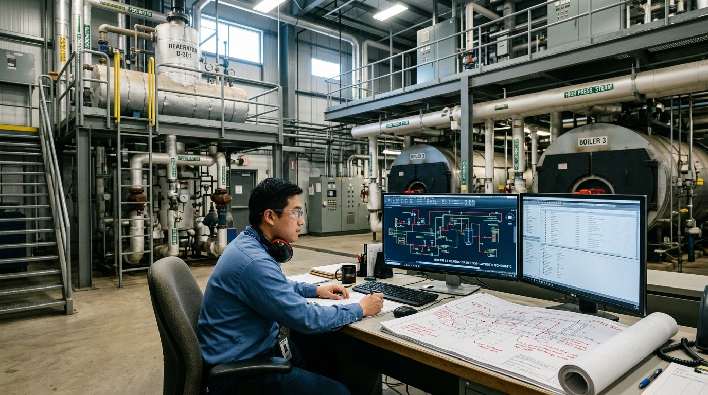
Updating central mechanical plant drawings is one of the most demanding tasks in mechanical drafting. When a boiler room layout undergoes revision, changes to the boiler feedwater deaerator and surge tank assemblies trigger cascading drafting updates across multiple plan sheets, detail elevations, and mechanical flow schematics. Senior mechanical engineers and CAD managers frequently find their teams bogged down manually rerouting high-pressure steam supply runs, boiler feed pump suction lines, overflow loops, and make-up water connections.
The Bottleneck in Boiler Feedwater and Deaerator CAD Revisions
In high-pressure and low-pressure steam plants, deaerator tanks must be elevated on structural steel or mezzanine platforms to supply sufficient net positive suction head (NPSH) to boiler feed pumps. Whenever a structural beam moves, an equipment vendor submittal alters nozzle orientations, or an engineer resizes the feed pump headers to mitigate cavitation risk, drafters face tedious manual adjustments in AutoCAD. A simple three-foot shift of a feedwater surge vessel requires updating suction piping, recirculating bypass lines, chemical feed injection quills, vent condenser exhausts, and associated valve trains across multiple DWG files.
Because these piping runs coordinate tightly with adjacent structural columns, catwalks, and steam headers, manual redlines often introduce unintentional misalignments. A drafter might update the pump suction drop on the enlarged mechanical room plan but miss updating the matching elevation view or line size annotations. The result is downstream drawing review cycles, unbudgeted drafting hours, and elevated stress during critical submittal milestones.
Why Traditional AutoCAD Scripts and Add-ons Fall Short
Engineering firms often attempt to accelerate mechanical plant drafting using custom AutoLISP routines, dynamic blocks, or complex third-party piping add-ons. While these tools assist during initial schematic routing, they struggle during iterative design updates. Scripts often break when encountering varying client layer standards, custom multi-view parts, or modified user coordinate systems (UCS). Furthermore, rolling out specialized software plugins creates an ongoing IT management headache for CAD managers who must test and maintain compatibility across diverse drafting stations.
When revisions arrive late in the design development phase, most MEP teams abandon complex macros and return to basic AutoCAD drafting commands like STRETCH, FILLET, and TRIM. Engineers spend valuable billable hours marking up redlines, while CAD drafters spend days tracing lines rather than focusing on higher-level system coordination.
Modernizing Plant Piping Updates with Plain-English AI Automation
MEP firms are finding a faster path forward by adopting plain-English drafting automation. Rather than relying on fragile scripts or cumbersome plugin rollouts, teams can now direct native drawing revisions using straightforward engineering instructions through AutoMEP.
AutoMEP connects engineering logic directly to AutoCAD DWG files through cloud-based automation. By analyzing the spatial layout of your mechanical room drawing, the AI understands equipment blocks, pipe centerlines, and connection nozzles. When a submittal changes, you simply describe the required adjustments in plain English. For example, you can instruct the system to relocate the deaerator vessel twenty-four inches south, align the transfer pump suction headers, maintain standard maintenance clearances from structural columns, and adjust line tagging accordingly. The platform carries out the geometric revisions directly inside the DWG file, preserving native entities, project layer conventions, and standard mechanical annotation styles.
Practical Steps to Accelerate Deaerator and Surge Tank Layout Updates
To reduce drafting backlog and maintain tight quality control across your central plant sets, consider adopting this streamlined revision workflow:
- Consolidate Vendor Nozzle Schedules Early: Verify nozzle elevations, flange ratings, and pump suction requirements against manufacturer cut sheets before executing batch DWG changes.
- Establish Explicit Equipment Clearance Polygons: Protect maintenance access zones for level gauges, relief valves, and pump motor service areas directly on designated non-plotting layers.
- Automate Iterative Routing Revisions: Use AutoMEP to shift equipment footprints and reroute connecting pipe runs simultaneously without redrawing individual fittings or rebuilding valve packages.
- Verify Sheet Consistency with Native Job Logs: Leverage comprehensive version histories and revision logs to confirm that matching pipe sizes, line tags, and valve symbols remain coordinated between floor plans and enlarged equipment details.
Scaling Mechanical Drafting Capacity Without Adding Headcount
Operations leaders and firm owners face constant pressure to deliver compressed submittal timelines without expanding drafting overhead. By delegating repetitive mechanical room geometry updates to plain-English automation, your engineers and senior designers retain full professional control over piping design while eliminating hours of low-leverage drafting rework. DWG deliverables remain clean, consistent, and strictly compliant with company CAD standards.
Whether you are revising central boiler plants, industrial steam headers, or commercial hydronic rooms, eliminating repetitive line work transforms project profitability. Discover how your team can execute precise, native AutoCAD revisions in minutes by visiting AutoMEP today.