How MEP Teams Can Update Chilled Beam Layouts and Secondary Hydronic Piping in AutoCAD Faster
AutoMEP Team,
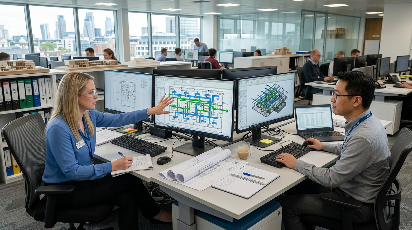
The High Friction of Chilled Beam Design Revisions in AutoCAD
Active and passive chilled beam systems deliver exceptional energy efficiency and indoor comfort, but drafting them in AutoCAD remains one of the most labor-intensive tasks for MEP design teams. Unlike conventional variable air volume terminals that terminate in flexible duct runs, active chilled beams require strict dual-service connectivity: dedicated primary outdoor air ductwork and two-pipe or four-pipe hydronic runouts. When an architect shifts a ceiling grid by six inches or an interior designer reconfigures room boundaries, every beam, transition, flexible hose connection, balancing valve, and runout pipe must shift in unison.
For MEP engineers, CAD managers, and drafting leads, these late-stage design iterations trigger disproportionate drafting rework. Drafters find themselves repeatedly stretching duct stubs, realigning pipe centers, reconnecting runout piping, repositioning circuit setters, and updating equipment identification tags across dozens of sheets. Because manual drafting under tight deadlines inevitably introduces disconnects, missing fittings, or mismatched tags, senior engineers spend valuable project hours auditing drawings instead of advancing engineering calculations.
Why Traditional AutoCAD Drafting Workflows Slow Down Chilled Beam Updates
In conventional AutoCAD environments, keeping chilled beam layouts coordinated requires meticulous manual manipulation across multiple disciplines. A single floor plan revision often forces drafting teams through a repetitive cycle of friction points:
- Dual-Discipline Rerouting: Adjusting chilled beam locations forces simultaneous modifications to both HVAC sheet layers and mechanical piping layers, multiplying drafting time across separate DWG files.
- Fittings and Valve Reconnection: Moving an active beam involves breaking, extending, and rebuilding copper supply and return connections along with strainers, shut-off valves, and balancing packages.
- Ceiling Grid Re-centering: Architectural reflected ceiling plan updates require precision snapping and re-centering across recessed beam slots, demanding tedious manual alignment.
- Annotation and Tag Disconnects: Relocating terminal units frequently orphans leader lines, airflow CFM annotations, hydronic GPM tags, and beam identification labels.
Writing custom AutoLISP routines or deploying complex desktop add-ins rarely solves this bottleneck. Scripted macros break when layer standards shift between projects, and rolling out heavy workstation plugins creates an administrative maintenance burden that CAD managers simply do not have time to support.
Streamlining Chilled Beam and Hydronic Edits with Natural-Language AI Automation
Engineering teams need a simpler path from revised design requirements to finished DWG updates without wrestling with programming code or software configuration headaches. Modern design automation from AutoMEP enables MEP firms to execute complex chilled beam and piping modifications using straightforward, natural-language instructions.
Instead of manually editing hundreds of individual linework elements, a CAD manager or design engineer can upload the active AutoCAD DWG file and describe the necessary revision. For example, you can specify: Shift active chilled beams in zones 201 through 214 to match the updated 2x4 ceiling grid, extend primary air duct runouts to center, and adjust the 3/4-inch chilled water supply and return branches to maintain 12-inch clear offsets from the lighting fixtures.
AutoMEP interprets the drawing geometry, identifies the relevant MEP components and blocks, and applies precise CAD edits directly within the native DWG file. The automation respects standard layer naming conventions, maintains pipe centerline integrity, updates associated flow annotations, and cleanly resolves component connectivity.
Operational Benefits for CAD Managers and MEP Firm Leadership
Adopting an AI-driven AutoCAD workflow transforms how engineering practices handle repetitive drafting cycles during design development and construction document revisions:
- Zero Workstation Rollouts: Because the system works directly with standard DWG files through the cloud, CAD managers avoid the hassle of deploying and troubleshooting desktop plugins or custom scripts across draftspersons' computers.
- Native AutoCAD Output: All modified ductwork, piping, valves, and text labels remain fully native AutoCAD entities, allowing anyone on the team or external partners using Autodesk AutoCAD to open, inspect, and modify files without proxy object warnings.
- Complete Drawing Auditability: Every automated revision generates comprehensive job logs and visual version history, allowing project managers to review every shifted beam and reconnected pipe runout before finalizing deliverables.
- Capacity to Scale Without Headcount Spikes: Engineering firms can comfortably absorb rapid tenant improvement changes and aggressive client turnaround requests without burning out drafting staff or relying on expensive third-party drafting outsourcing.
Accelerating Project Turnaround While Protecting Engineering Control
When engineering firms eliminate manual drafting bottlenecks, senior engineers retain technical control while dramatically shortening turnaround intervals. Routine chilled beam shifts that once consumed two days of tedious manual drafting can now be completed, verified, and ready for quality control in a fraction of the time. Drafters and designers are freed from repetitive linework manipulation, allowing them to focus on clash detection, energy modeling, and higher-value coordination tasks.
Discover how your team can eliminate repetitive DWG revisions and modernize MEP drawing maintenance by visiting AutoMEP today.