How MEP Teams Can Update Generator Fuel Oil Piping Layouts in AutoCAD DWG Files Faster
AutoMEP Team,
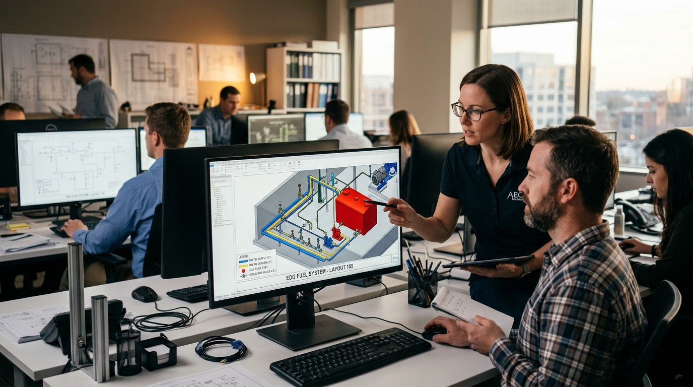
Standby emergency power systems are vital infrastructure in hospitals, data centers, and commercial facilities. When standby generator locations change, underground storage tank capacities increase, or fuel polishing systems are added, mechanical engineers face demanding drafting revisions in AutoCAD DWG files.
Designing generator fuel systems requires balancing supply piping, overflow return lines, emergency vent headers, day tank fill circuits, and double-wall containment geometry. Because fuel piping is strictly governed by environmental containment codes and NFPA 30 / NFPA 110 standards, minor equipment moves trigger tedious drawing revisions across mechanical site plans, generator room layouts, and piping schematics.
The High-Stakes Friction in Fuel Oil Piping Revisions
Fuel oil piping design involves multiple interconnected subsystems that must remain perfectly coordinated across every drawing view:
- Supply and Return Loops: Supply lines from bulk storage tanks to day tanks must coordinate with return overflow piping, pressure relief valves, and duplex pump sets.
- Secondary Containment and Leak Detection: Double-wall pipe runs, containment sumps, and interstitial leak monitoring probes require exact dimensional annotations across floor plans and trench details.
- Day Tank Clearances and Venting: NFPA 110 mandates dedicated clearances around day tanks, solenoid shutoff valves, and exterior normal/emergency vent piping.
- Cross-Discipline Coordination: Fuel supply trenches must not conflict with structural grade beams, electrical conduits, or underground storm drainage lines.
In traditional firm workflows, updating a fuel oil system requires senior drafters to manually delete pipe centerlines, redraw fittings, reposition valve symbols, and rewrite schedule callouts across multiple DWG drawing files.
Accelerating Fuel Oil DWG Revisions with Natural-Language Automation
Modern CAD automation removes repetitive manual drafting from fuel system design. With AutoMEP, MEP firms can update piping layouts, day tank connections, and fuel system details in native AutoCAD DWG files using simple natural-language instructions.
Engineers and CAD coordinators simply describe the required modification:
- "Reroute the 2-inch double-wall fuel supply line from the bulk storage tank along the south wall trench, maintaining 6 inches of clearance from the electrical cable tray."
- "Update the day tank pump suction manifold to include a duplex strainer assembly, reposition the emergency shutoff valve block, and update line size callouts."
- "Adjust the emergency vent pipe run to route vertically along the exterior facade, add a rain cap detail block, and update penetration sleeve notes."
AutoMEP analyzes the spatial geometry of your AutoCAD drawing and automatically applies the edits directly into native DWG entities, preserving firm layer naming, line types, and dynamic block attributes.
Empowering Engineering Teams to Deliver Faster
By automating routine AutoCAD modifications, MEP firms reduce drafting backlogs and eliminate costly coordination mistakes. Built-in revision tracking and detailed job logs give senior mechanical engineers total confidence that drawing deliverables remain accurate and code-compliant.
Free your engineering team from repetitive drafting tasks and accelerate your project delivery cycles. Visit AutoMEP to see how natural-language CAD automation can transform your mechanical drafting workflow.