How MEP Teams Can Update Hydronic Expansion Tank Layouts in AutoCAD DWG Files Faster
AutoMEP Team,
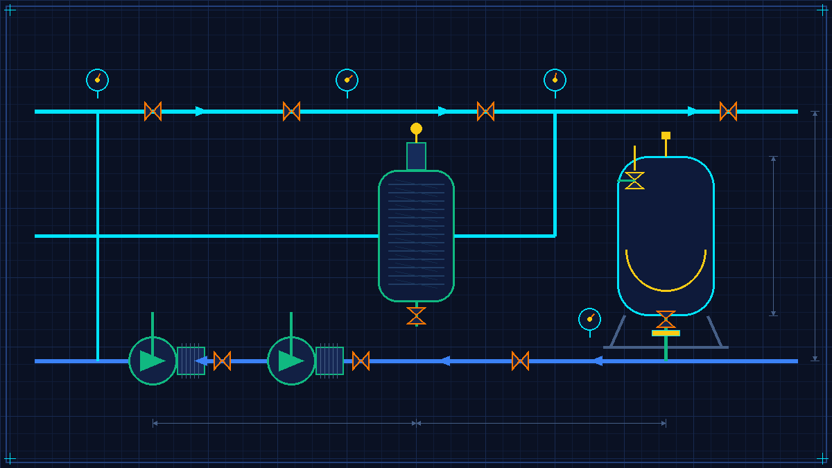
Commercial hydronic heating and chilled water systems require precise pressure control and thermal expansion compensation to protect boilers, chillers, and distribution piping from overpressure failures. When central plant heating loads change, building volume calculations expand, or equipment manufacturers modify tank physical dimensions, mechanical engineers and CAD technicians face tedious drafting revisions in AutoCAD DWG files.
Coordinating hydronic expansion tanks and tangential air separators inside compact mechanical penthouses and boiler rooms is notoriously space-restricted. A single capacity increase or bladder tank relocation triggers cascading adjustments across primary-secondary piping headers, safety relief valve discharge lines, system makeup water connections, and floor-mounted seismic restraint details. For engineering leaders and CAD managers, manually executing these repetitive geometry and tag changes consumes valuable billable hours and delays project delivery milestones.
The Drafting Bottlenecks of Hydronic Expansion and Air Separation Revisions
Proper hydronic design demands rigid adherence to ASHRAE guidelines, ASME Section VIII pressure vessel codes, and point-of-no-pressure-change (PONPC) engineering principles. When mechanical room layouts shift during design development, CAD teams encounter several recurring coordination hurdles:
- Point of No Pressure Change (PONPC) Relocation: Diaphragm expansion tanks must connect directly to the suction side of circulating pumps to prevent pump cavitation. Shifting pump headers requires manual recalculation and redrawing of expansion pipe branches and isolation lockouts.
- Air Separator and Dirt Collector Clearances: Tangential air separators require strict upstream and downstream laminar flow straight-pipe runs and vertical clearance for automatic float vents and bottom blowdown valves.
- Safety Relief and Make-up Water Synchronization: Expansion tank updates alter safety relief valve setpoint sizing, backflow prevention assemblies, and cold water fill line routing, requiring edits across multiple drawing sheets.
- Multi-Sheet Callout Discrepancies: Tank revisions affect mechanical room plan views, enlarged equipment sections, P&ID schematics, and mechanical equipment schedules. Manually updating each drawing view creates risk of inconsistent tag references.
When drafting teams rely on manual vector trimming, stretching, and re-annotating in AutoCAD, project turnarounds slow down significantly.
Accelerating Hydronic DWG Revisions with Natural-Language CAD Automation
Rather than manually adjusting lines, arcs, and valve blocks across multiple drawing files, mechanical teams can execute rapid, standard-compliant updates using AutoMEP. AutoMEP uses spatial engineering intelligence to translate natural-language project instructions into native AutoCAD drawing modifications.
Mechanical designers simply describe the required engineering revision:
- "Replace the 200-gallon vertical expansion tank on Sheet M-201 with an ASME 350-gallon diaphragm vessel, adjust seismic base curb dimensions, and update the suction pipe connection to 2-1/2 inches."
- "Relocate the tangential air separator 3 feet west along the main chilled water supply header, preserve a 24-inch clearance above the automatic air vent, and realign the blowdown drain line."
- "Batch update all expansion tank tags, acceptance volumes, and pre-charge pressure ratings on the enlarged boiler room plan to match the revised equipment schedule."
AutoMEP interprets the spatial relationships in your DWG files and writes changes directly into native AutoCAD objects without requiring client-side plugins, custom AutoLISP macros, or complex software installations.
Ensuring Uncompromised Quality and Complete Traceability
Automating repetitive AutoCAD modifications gives engineering firms predictable turnaround times and complete design integrity:
- Native AutoCAD Geometry: All modified lines, blocks, dimensions, and schedule annotations remain 100% native DWG entities, guaranteeing seamless collaboration with external architects and consultants using AutoCAD.
- Comprehensive Job Logs: Every automated edit generates full audit trails and version histories, giving senior mechanical engineers total transparency to review and approve drawing changes before issuing submittal sets.
- Elimination of Script Maintenance: Because AutoMEP handles drawing operations in the cloud, CAD managers avoid the burden of managing local script libraries or troubleshooting software compatibility issues.
Transform Your Mechanical Drafting Workflow Today
Updating hydronic expansion tank layouts, air separators, and central plant mechanical drawings should not create bottlenecks for your design team. By automating routine CAD modifications with natural-language instructions, your firm can accelerate project turnaround, eliminate drafting rework, and scale engineering capacity.
Experience how simple and efficient AutoCAD MEP drafting can be. Visit AutoMEP today to explore natural-language AI automation built specifically for modern MEP engineering teams.