How MEP Teams Can Update Oil-Water Separator and Sand Interceptor Layouts in AutoCAD DWG Files Faster
AutoMEP Team,
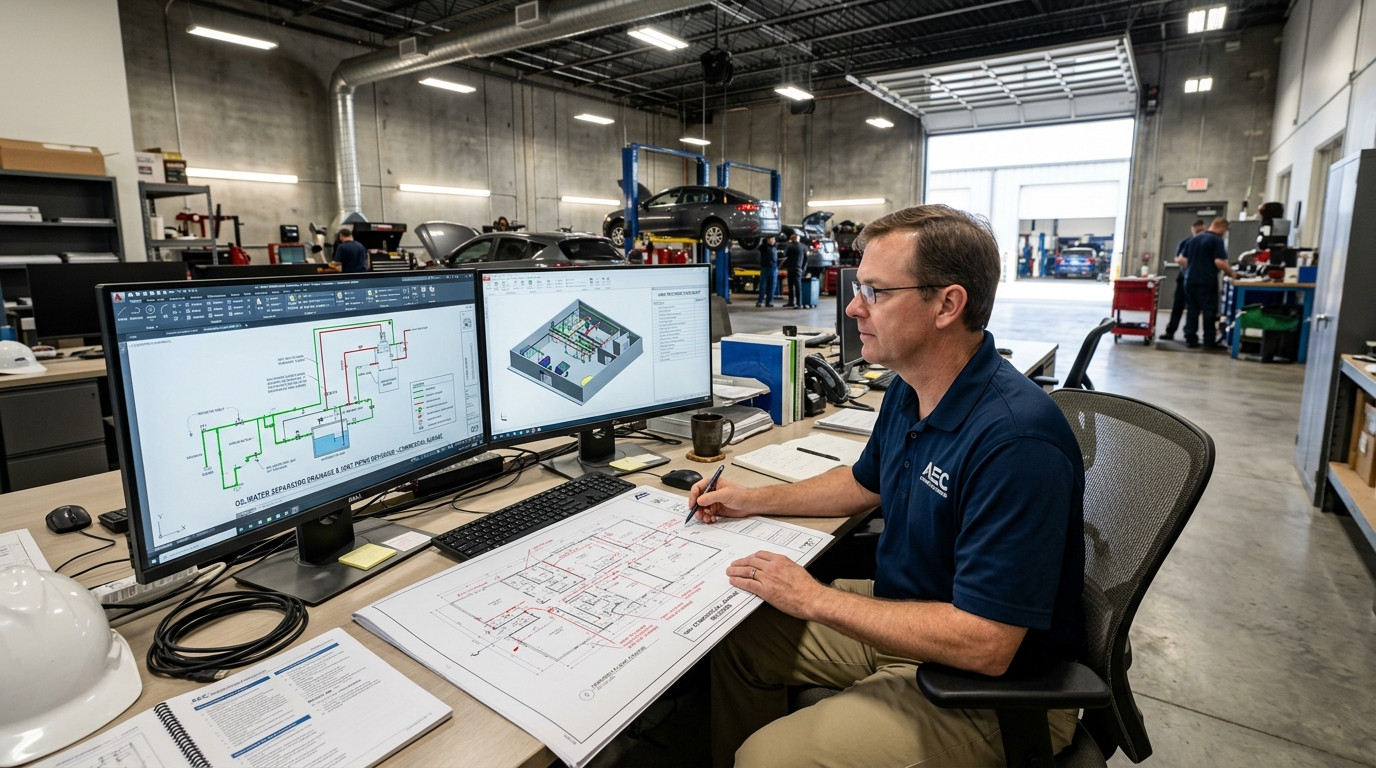
Updating oil-water separator and sand interceptor layouts is among the most tedious drafting chores in commercial and light industrial plumbing design. Whether you are delivering plans for a vehicle maintenance garage, a transit fleet depot, an aircraft hangar, or a structured parking facility, oily waste drainage systems require strict engineering rigor. When an architect shifts an overhead door, a structural engineer relocates a column footing, or a civil consultant revises the exterior utility invert, plumbing designers face hours of manual AutoCAD drafting just to keep tributary trench drains, interceptor basins, and gravity lines aligned.
For plumbing engineers, CAD managers, and drafting leads, these revisions often mean redrawing long pipe runs, recalibrating gravity slopes, shifting cleanouts, adjusting independent vent stacks, and re-annotating flow capacities across multiple drawing sheets. Without a way to execute these routine geometry updates quickly, late-stage coordination changes quickly eat into project profit margins.
The Repetitive Bottlenecks in Drafting Oil-Water Separator Systems
Oil-water separators and sand interceptors operate under strict gravity drainage rules and specialized environmental plumbing codes such as Chapter 10 of the International Plumbing Code (IPC) and the Uniform Plumbing Code (UPC). Unlike pressurized domestic water systems, a minor spatial relocation of a catch basin or interceptor unit triggers a chain reaction across the entire DWG file:
- Recalculating Gravity Slope Inverts: Interceptor inlet and outlet inverts dictate the entire downstream and upstream pipe network. Moving a separator even five feet away from the exterior wall changes running pipe footage and invert calculations, forcing drafters to manually recalculate elevations and modify annotations on plan views and details.
- Managing Dedicated Venting Requirements: Oil-water separators demand dedicated vapor vents that cannot simply tie into general sanitary vents due to volatile hydrocarbon fumes. When interceptors shift, drafters must manually reroute dedicated vent lines through wall cavities or chase spaces to approved roof termination zones.
- Coordinating Sand and Grit Interceptor Stages: Heavy-duty vehicle bays often pair sand and grit interceptors in series ahead of oil-water separation tanks. Moving one chamber means shifting interconnecting piping, sampling manholes, shutoff valves, and structural maintenance access clearances.
- Re-tagging Equipment Attributes and Callouts: Model numbers, liquid holding capacities, GPM retention rates, and invert depths must remain coordinated between plan callouts, riser schematics, and equipment schedules. Manual text editing across multiple views introduces avoidable transcription mistakes.
Why Traditional Scripting and Generic CAD Tools Fall Short
Many CAD managers attempt to streamline separator revisions using custom AutoLISP routines or dynamic blocks. While dynamic blocks work well for placing a standard tank outline, they break down when handling sloped drainage connectivity, multiline offset routing, or coordinate alignment across disparate architectural background revisions. Maintaining custom LISP scripts requires specialized programming hours, regular debugging across new AutoCAD releases, and constant maintenance that busy CAD managers rarely have time to support.
Outsourcing redlines to third-party drafting services introduces its own set of risks. Outside detailers often overlook critical code requirements, such as minimum water seal depths, required sampling tee orientations, or maintenance clearance perimeters. The engineering team spends more time redlining markups and catching basic coordination blunders than it would take to execute the drafting in-house.
How Plain-English AI Updates Oil-Water Separator Drawings in Minutes
Modern engineering firms are eliminating repetitive manual DWG drafting bottlenecks by introducing automated, plain-English drawing workflows. Rather than navigating nested dialog boxes or redrawing sloped lines vertex by vertex, teams can state intended revisions in clear engineering terms.
Using AutoMEP, plumbing teams upload their active AutoCAD DWG file and describe the necessary modification in plain language. For example, a designer can enter a prompt such as: 'Relocate the sand interceptor and oil-water separator package 6 feet west along grid line B, maintain a 1/4 inch per foot slope on incoming trench drain waste lines, shift the sampling tee and cleanout access covers to match, and adjust the dedicated vent run to rise inside partition wall W-104.'
AutoMEP interprets the drawing spatial data directly, recognizes the pipe components and interceptor blocks, and executes the geometry updates natively inside the DWG file. The output preserves your existing company layer standards, linetypes, dimension styles, and block definitions without requiring anyone to write code or configure complex macros.
A Predictable Workflow for Plumbing Drainage Revisions
Adopting an automated revision workflow allows MEP firms to handle late-stage contractor submittal changes and client requests with speed and control:
- Step 1: Upload the Current DWG: Bring your working plumbing drawing into AutoMEP directly through your browser, avoiding workstation plugin deployments.
- Step 2: Provide Plain-English Redline Instructions: Direct the necessary equipment movements, pipe size updates, slope adjustments, and callout modifications exactly as you would describe them to an experienced drafting technician.
- Step 3: Review the Automated Execution: AutoMEP adjusts pipe lengths, updates inverts, shifts connected fittings, and repositions annotation callouts natively within the DWG.
- Step 4: Audit Changes with Job Logs and Version History: Verify every revised component through clear revision histories and job summaries, ensuring complete quality assurance before issuing sheets to the field.
Scale Drawing Output Without Increasing Headcount
Drafting oil-water separator installations, sand interceptors, and hazardous waste drainage connections should not tie up your senior plumbing designers in mechanical mouse clicking. By removing the friction of repetitive geometry edits, your team spends less time redrawing pipe runs and more time evaluating hydraulic loads, environmental compliance, and site utility coordination.
Because AutoMEP operates seamlessly in the cloud without requiring software installations or plugin rollouts, CAD managers can standardize repetitive drawing updates across their entire firm immediately. Your drawings stay clean, revisions remain fully auditable, and projects proceed on schedule without burning out your drafting staff.